I’ve always been fascinated by robots of all kind, and through my undergraduate research project at University of Colombo I was able to explore simulating the movement of a snake-like robot. Before I dive into the weeds of how this was carried out, below are some prerequisites on the simulation platform Gazebo used in this work.
Prerequisites
Gazebo is an open source software platform widely used in robotic simulations. If you’ve never used Gazebo then click here. The official website has all the instruction on how to install Gazebo and tutorials on how to get started. If you are new to robotics in general I’d suggest following through the book Theory of Applied Robotics: Kinematics, Dynamics and Control.
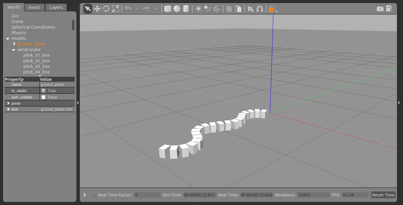
The serial snake robot model
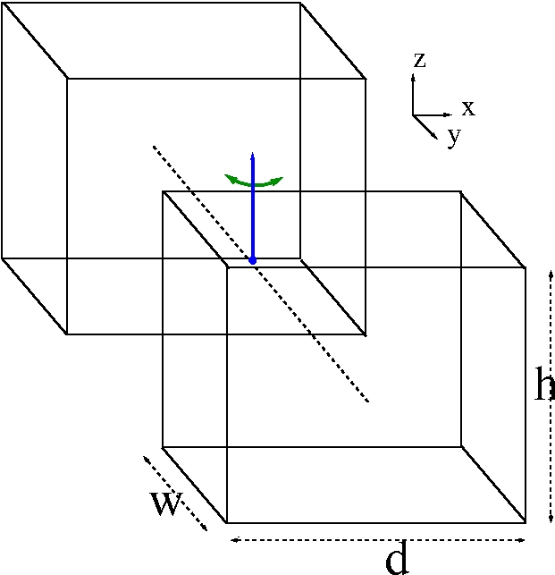
I made some assumptions when designing this initial snake robot, purely to reduce the complexity of the motion. I assumed that biological snakes move in a planar surface (2D) replicating a sinusoidal pattern, that scales don’t contribute to overall motion and that a snakes body could be approximated by a linear combination of cuboids which are linked by revolute joints which rotate about the Z axis as shown below.
  <!-- ------------ serial link 17 ---------- -->
  <link name="plink_17_box">
    <pose>0 -1.60 0.05 0 0 0</pose> <!-- changes with -0.10 for each  y coord -->
    <inertial>
      <inertia>
        <ixx>0.00018625</ixx> <!-- using tensor matrix -->
        <iyy>0.00025</iyy>
        <izz>0.00018625</izz>
        <ixy>0</ixy>
        <ixz>0</ixz>
        <iyz>0</iyz>
      </inertia>
      <mass>0.15</mass>
    </inertial>
    <collision name="collision">
      <geometry>
        <box>
          <size>0.1 0.07 0.1</size>
        </box>
      </geometry>
    </collision>
    <visual name="visual">
      <geometry>
        <box>
          <size>0.1 0.07 0.1</size>
        </box>
      </geometry>
    </visual>
  </link>
The twist motion of the joints in the robot is numerically identified by integer values from +2 and -2, that represent the maximum/minimum twist to the left and right respectively and +1,-1 which represents the twist to the left & right for half the maximum angle. For this preliminary study, the maximum and minimum twist angles are defined as below.
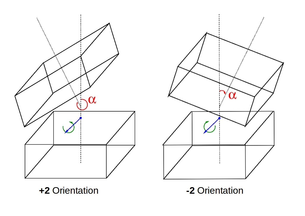
| Operation | Twist Direction | Angle(\(\alpha\)) |
|---|---|---|
| +2 | Left | 335\(^{\circ}\) |
| +1 | Left | 342.5\(^{\circ}\) |
| -1 | Right | 12.5\(^{\circ}\) |
| -2 | Right | 25\(^{\circ}\) |
<!-- code for joint between link 5 and 6 -->
<joint name="plink_6_MOVE" type="revolute">
  <pose>0 -0.0525 0 0 0 0</pose> <!-- position relative to head -->
  <child>plink_05_box</child>
  <parent>plink_06_box</parent>
  <axis>
    <xyz>0 0 1</xyz> <!-- rotating axis is Z -->
    <limit>
      <lower>-0.436332</lower> <!-- upper limit for alpha in radians -->
      <upper>0.436332</upper> <!-- lower limit for alpha in radians -->
    </limit>
  </axis>
</joint>
The code snippets below show the implementation for these twist like motions for each joint within the main plugin for the model.
void movementPlugin::moveJointLeft(int _jointPos) // +2 orientation
{
	math::Angle currentAngle = this->joints[_jointPos]->GetAngle(0);
	if(currentAngle <maxLimit ){
		joints[_jointPos]->SetForce(0,10);//left
	}
}

void movementPlugin::moveJointRight(int _jointPos) // -2 orientation
{
	math::Angle currentAngle = this->joints[_jointPos]->GetAngle(0);
	if(currentAngle >minLimit ){
		joints[_jointPos]->SetForce(0,-10);//right
	}
}

void movementPlugin::shrinkJoint(int _jointPos) // -1 & +1 orientation
{
	math::Angle currentAngle = this->joints[_jointPos]->GetAngle(0);
	math::Angle upper = maxLimit/2;
	math::Angle lower = minLimit/2;
	if(currentAngle < lower ){
		joints[_jointPos]->SetForce(0,-10);
	}else if(currentAngle >upper){
		joints[_jointPos]->SetForce(0,10);
	}
}
Instead of defining a sinusoidal movement pattern for the overall robot, the movement is replicated by creating 8 states or orientations for the complete snake robot, where those states would be iteratively executed until we need the robot to stop. Note that there is no feedback loop here, and neither dose the robot know where it’s going. The idea I wanted to test out here was the possibility of creating complex motion patterns (Lateral Undulation in this case) without the need for equations of motion or any sort of computation.
As per the code below for ease of execution the entire snakes body of 20 joints is broken into 4 main segments, namely head(M1-M5), body1(M6-M10), body2(M11-M15), tail(M16-M21) where the operations of either moveJointRight(), moveJointLeft() or shrinkJoint() would be executed for a complete segment at a given iteration of the loop.
// for all these functions k represents the index to start
// and limit the number of joints to execute the movement function
void movementPlugin::left(int k,int limit)
{
	for(int i=0;i<limit;i++){
		//int loc=lamdaLimit[0][k]-i; //  B->F
		int loc=lamdaLimit[0][k]+i; //    F->B
		moveJointLeft(loc);
	}
}

void movementPlugin::right(int k,int limit)
{
	for(int i=0;i<limit;i++){
		//int loc=lamdaLimit[0][k]-i; //  B->F
		int loc=lamdaLimit[0][k]+i; //    F->B
		moveJointRight(loc);
	}
}

void movementPlugin::shrink(int k,int limit)
{
	for(int i=0;i<limit;i++){
		//int loc=lamdaLimit[0][k]-i; //  B->F
		int loc=lamdaLimit[0][k]+i; //    F->B
		shrinkJoint(loc);
	}
}
The Table below represents the states and the code that transitions each segment of the robot. For every 150 iterations the sequence jumps one step forward(1->2 ect). Of all the 8 states, the first 4 are the initial configurations. These configurations (Config 1-4) were used to set initial positions of the links such that a stationary sine wave was shown when considering the overall snake robot shape. Afterwards the configurations from 5-8 were iteratively looped with each update cycle in the plugin.
| Configurations | Head (M1-M5) | Body1 (M6-M10) | Body2 (M11-M15) | Tail (M16-M21) |
|---|---|---|---|---|
| Configuration 1 | +2 | |||
| Configuration 2 | +2 | -1 | ||
| Configuration 3 | +2 | -1 | -2 | |
| Configuration 4 | +2 | -1 | -2 | +1 |
| Configuration 5 | -1 | -2 | +1 | +2 |
| Configuration 6 | -2 | +1 | +2 | -1 |
| Configuration 7 | +1 | +2 | -1 | -2 |
| Configuration 8 | +2 | -1 | -2 | +1 |
// The OnUpdate() function runs continuously
void movementPlugin::OnUpdate()
{
	//------[ B1-> B2 -> B3 -> B4 ]---------------------------
	//-------initial config (1-4)-----------------------------
	if(initialConfigCount<150){
		left(k0,5);
		initialConfigCount++;
	}else if(initialConfigCount<300){
		shrink(k0,5);
		left(k1,5);
		initialConfigCount++;
	}else if(initialConfigCount<450){
		right(k0,5);
		shrink(k1,5);
		left(k2,5);
		initialConfigCount++;
	}else if(initialConfigCount<600){
		shrink(k0,5);
		right(k1,5);
		shrink(k2,5);
		left(k3,5);
		initialConfigCount++;
	}else{
	//-------continues config (5-8)-------------------------
		if(sequenceCount==0){
			left(k0,5);
			shrink(k1,5);
			right(k2,5);
			shrink(k3,5);
			count++;
		}else if(sequenceCount==1){
			shrink(k0,5);
			left(k1,5);
			shrink(k2,5);
			right(k3,5);
			count++;
		}else if(sequenceCount==2){
			right(k0,5);
			shrink(k1,5);
			left(k2,5);
			shrink(k3,5);
			count++;
		}else if(sequenceCount==3){
			shrink(k0,5);
			right(k1,5);
			shrink(k2,5);
			left(k3,5);
			count++;
		}
	}
	//----------seconds counter-----------------------
	if(count>150){
		count=0;
		sequenceCount=(sequenceCount+1)%4;
	}
}
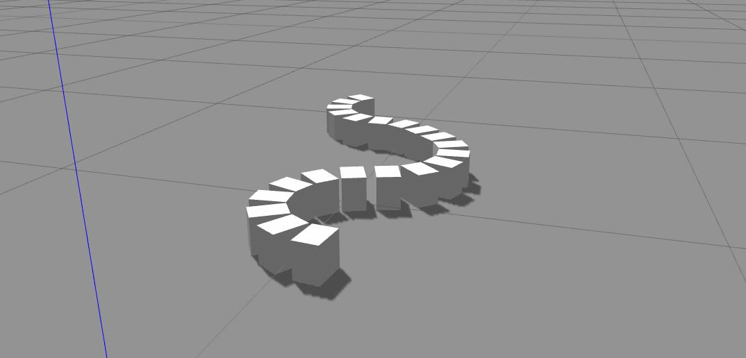
And that’s it, The gif below shows the snake robot simulation as described by the code above. This proof-of-concept shows that it is in-fact possible to replicate complex biological motion from simple methods like. However, this is far from perfect, right now this snake has no idea where it’s going, and neither is it capable of controlling its speed or optimizing its movement based on environmental constraints. If you’d like to work on this code or need this for some other project feel free to get it from here.
Cheers!
Next: Image processing with Matlab: Combining video-game sprites
Prev: Hello world :)